Clymer, 1972 ("Volkswagen Service Repair Handbook...")
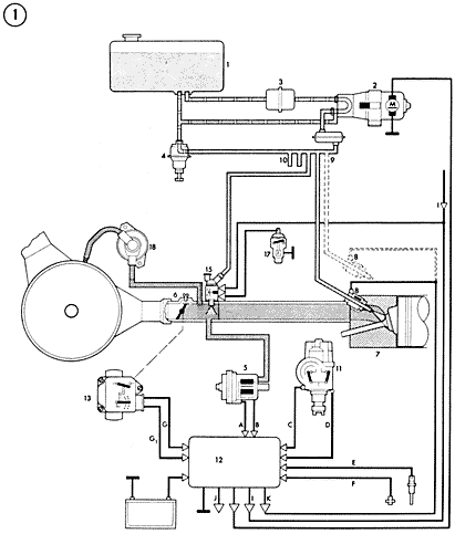
Chapter 7, Figure 1

1. Fuel tank
2. Electric fuel pump
3. Fuel filter
4. Fuel pressure regulator
5. Pressure sensor
6. Air intake distributor
7. Cylinder head
8. Fuel injectors
9. Fuel loop line
10. Connection for fuel line (cold starting)
11. Ignition distributor with trigger contacts
12. Electronic control unit
13. Throttle valve switch with power mixture enrichment
15. Cold starting jet
16. Electro-magnetic valve (cold starting)
17. Temperature switch (cold starting)
18. Auxiliary air regulatorA and B. Signals from pressure sensor
C and D. Signals from trigger contacts
E and F. Signals from temperature sensors (warming up phase)
G. Signal from throttle valve switch (fuel shut off on overrun)
G1. Power mixture enrichment
1. Signal from starter (term 50)
J. Signal to injectors 1 and 4
K. Signal to injectors 2 and 3
Copyright Clymer Publications, Overland Park, Kansas.
Used with permission.